Basic HTML-Version


90
TELE-satellite International — The World‘s Largest Digital TV Trade Magazine
— 02-03/2012
— www.TELE-satellite.com
Add-On for SPAUN Signal Analyzers
A waterfall diagram displays a spec-
trum over a specific time period. This
makes it possible to chronicle the spec-
trum of a reception system while, for
example, the antenna is being moved.
We already reported on a software so-
lution in the 12-01/2012 issue of TELE-
satellite but there‘s also a solution for
those signal analyzers that don‘t have a
spectrum output.
We already introduced the high-end
SPAUN SPAROS 609 satellite signal an-
alyzer to you back in the TELE-satellite
08-09/2009 issue. It has been regularly
updated by SPAUN, for example, with a
WiFi receiver. The test report for that
version appeared in the TELE-satellite
08-09/2010 issue.
Real-time Waterfall
Diagram Plus High
Resolution with the
SPAROS 609
Vitor Martins Augusto
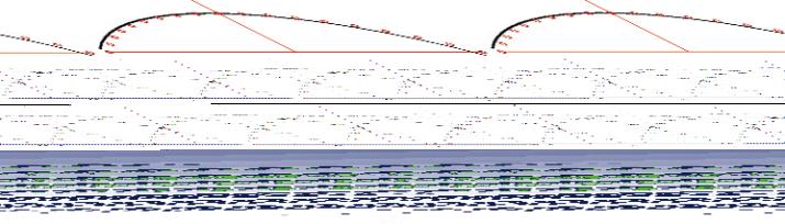
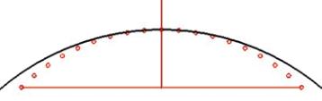
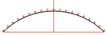
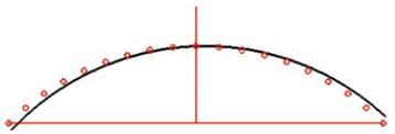
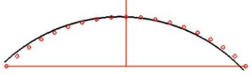
Figure 1: Typical problems with the alignment of a motorized satellite antenna system
Incorrect adjustment of the motor and antenna
Too Large
Too Small
Inclination
of the motor
axis
Satellites on outer edge of arc are not
received (Antenna too high)
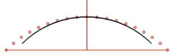
Satellites on outer edge of arc are not
received (Antenna too low)
Inclination
of the
antenna
All satellites are not received
(Antenna too high)
All satellites are not received
(Antenna too low)
Motor
Alignment
Satellites to the left are not received
because antenna is too low, Satellites
to the left are not received because
antenna is too high
Satellites to the left are not received
because antenna is too high, Satellites
to the left are not received because
antenna is too low
AROS 609 anyway, a rather exotic so-
lution was invented. An HD compatible
webcam can film the screen on the SP-
AROS 609 and then the video can be
graphically analyzed in real time on a
PC so that the spectrum can be ex-
tracted.
This solution makes it possible to cre-
ate a high-resolution waterfall diagram
in real time. The purpose of this test re-
port is to develop an easy, reproducible
procedure for the documentation and
alignment of motorized satellite sys-
tems. To be able to set up these types
of systems properly, three parameters
must be correctly configured:
•
Inclination of the motor axis
•
Inclination of the antenna
•
Alignment of the motor with
the antenna
If a motorized system like this is in-
correctly aligned, it would lead to the
following typical situations depending
on which of the three parameters are
not properly set up (see the Figures).
actually makes sense considering that
the resolution of the PAL signal would
not be able to properly display the
spectrum; and it‘s not even necessary
since this unusual signal analyzer uses
a high-resolution LCD screen.
In order to build a waterfall diagram
with the spectrum of the SPAUN SP-
The
SPAROS
609 comes with
numerous func-
tions and it‘s ex-
tremely easy and
logical
opera-
tion lets the user
quickly get the
desired results.
Especially impres-
sive is the spec-
trum analyzer dis-
play. The satellite
frequency spec-
trum is presented
in high resolution
and also in real
time thus making
it an ideal base
for a waterfall dia-
gram.
Even
though
this analyzer has
a composite video
output, it is not
appropriate
to
make the spec-
trum available at
this output. This
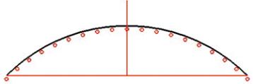
Correct alignment of the motor and antenna:
all of the satellites are located precisely
on the motor‘s travel arc
1