Basic HTML-Version


52
TELE-satellite International — The World‘s Largest Digital TV Trade Magazine
— 02-03/2012
— www.TELE-satellite.com
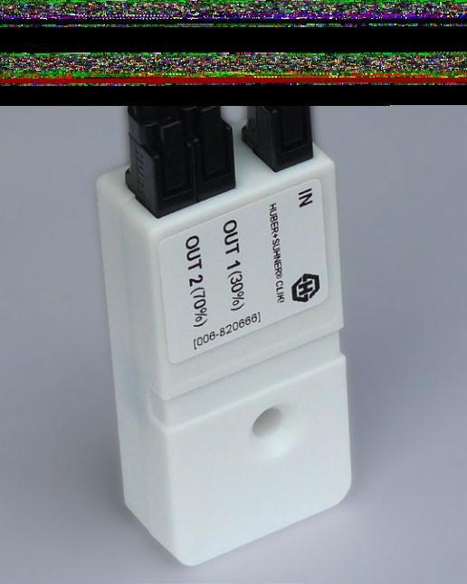
the whole system in which
Huber+Suhner CLIK! Splitter
Box is used. Our test system
included: 90cm dish aimed
at HOTBIRD satellite on 13°
E, an optical LNB, optic fib-
er cable, optic splitter and
optic-to-RF signal converter
(re-modulator) that was de-
livering the IF signal suitable
for a satellite receiver. The
optical LNB generated light
in the 1310 nm band. The
light carrier was modulated
with 0.95-5.45 GHz RF signal
which was Ku-Band low and
high sub bands of both po-
larizations stacked one over
the other.
We tested 5 CLIK! Splitter
Box models. The table below
presents the insertion losses
specified in manufacturer
data.
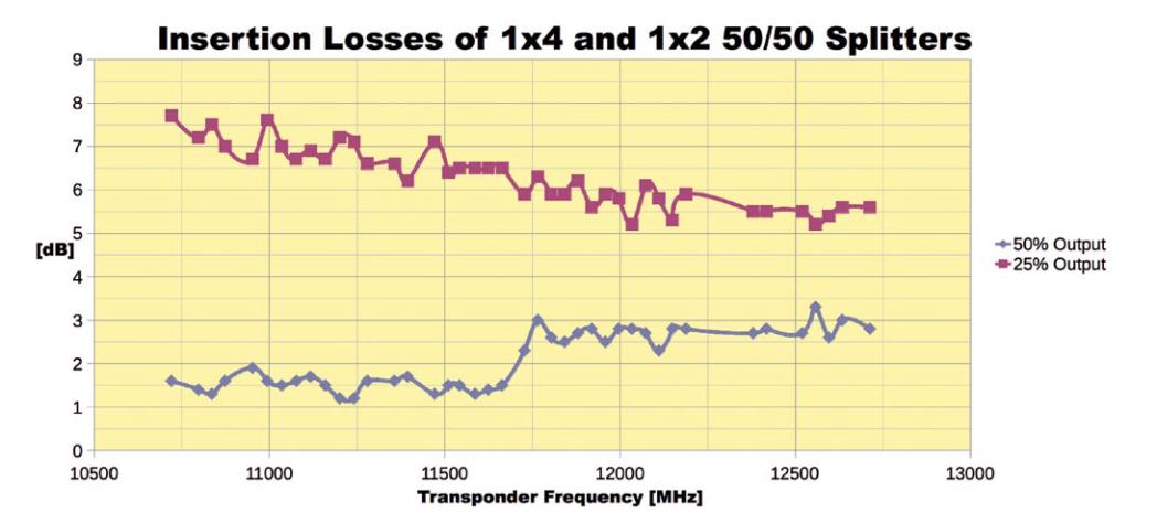
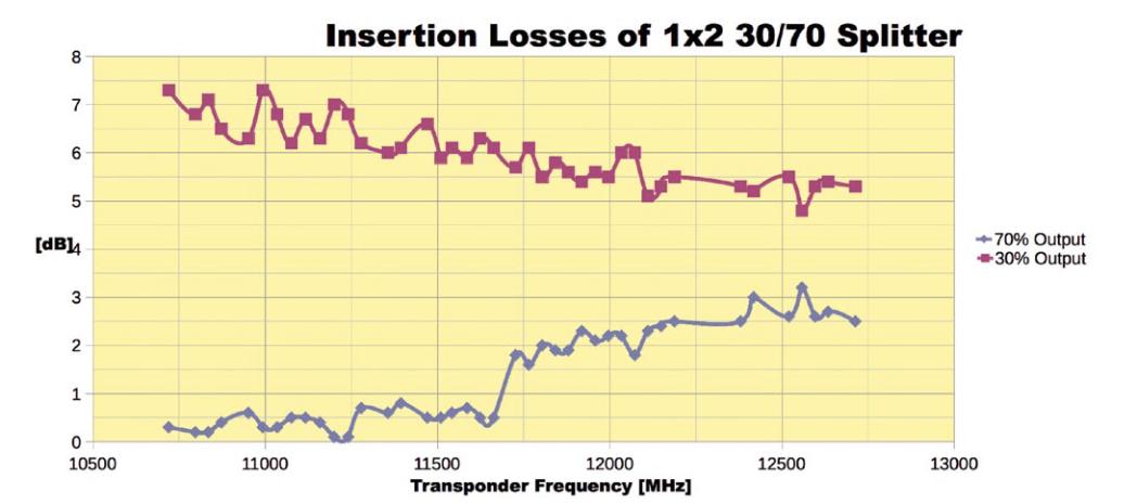
You can see the results in
the attached graphs. Please
mind that on top of the op-
tic splitter losses, there are
losses caused by nonlinear
transfer function of the op-
tic-to-RF signal converter.
Because of that, the losses
for 10, 20 and 30% outputs
may appear slightly higher
than specified for certain
frequencies. This is due to
Splitting ratio
% 2 x 50 30/70 20/80 10/90 4 x 25
Maximum
Insertion loss
dB 3.8 each 6.3/2.1 8.4/1.4 12.0/0.8 7.7 each