Basic HTML-Version


02-03/2012
50
TELE-satellite International — The World‘s Largest Digital TV Trade Magazine
— 02-03/2012
— www.TELE-satellite.com
Huber+Suhner CLICK!
Perfect solution to distribute the full
satellite signal to a multitude of receivers
Even Simpler to Use
Than Regular RF Splitters
Digital TV signal distribu-
tion is more and more often
based on fiber optics. Among
the most important advan-
tages of such solutions are:
extremely low signal losses
in fiber optic cables and wide
frequency bandwidth. The
latter feature makes it pos-
sible to distribute the whole
Ku-Band in one band without
the need to select polariza-
tion or low/high sub-band.
There are already LNBs with
optical output available on
the market, as well as com-
plementary optic to RF con-
verters (re-modulators) -
see the many reports on this
subject in previous TELE-
satellite issues. Fiber optic
cables have been in use for
many years now. The last
components you must use
to build a fiber optic satellite
TV signal distribution net-
work are optical splitter. And
this test report is just about
them.
The function of an optical
fiber splitter is analogous to
a familiar RF splitter. Most
of them direct part of the
incoming signal to the “tap”
output where the terminal
device is connected and the
other part to the “trunk”
output to which the remain-
ing part of the cable network
is connected. There are also
splitters that divide evenly
the input into two, four or
more outputs. Depending on
the network structure and
the splitter position in the
network, we need splitters
with different split ratios.
Huber+Suhner have vari-
ous models in their portfolio.
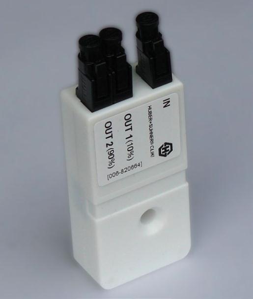
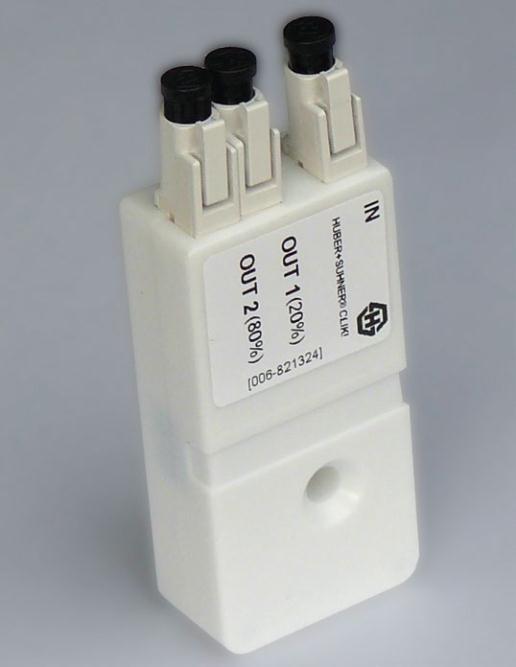
For this report, we have re-
ceived optical splitters with
the following split ratios: a
four output model (1x4) with
25%-25%-25%-25% ratio,
and a number of two output
models (1x2) with the follow-
ing ratios: 50%-50%, 30%-
70%, 20%-80% and 10%-
90%.
Apart from the splitters,
Huber+Suhner offered us a
selection of their excellent
fiber optic cables and connec-
tors, so that we were able to
build a small network using
only their components. All
components were perfectly
finished off and the splitters
were clearly labeled. You will
not have any doubt how to
hook them up. In contrast
to the RF stuff with F type
connectors, you do not have
to hurt your fingertips when
connecting everything to-
gether in fiber optic instal-
lations. Just a delicate push,
you hear a click and a fiber
optic cable is connected to a
splitter. Now you may guess
why Huber+Suhner branded
their new system CLIK!
TELE-satellite
readers
more familiar with insertion
losses expressed in decibels
rather than the signal power
percentage description of
the splitter outputs may at
first feel slightly uncomfort-
able. But take it easy. One
corresponds precisely to the
other. We can easily convert
original percentage values to
familiar “tap loss” and trunk
“loss figures” in decibels -
see the table.
We spent some time won-
dering what to measure to
make our test results as
practical for our readers
as possible. We decided to
measure rather the RF sig-
nal that will be fed to the
receiver IF input than opti-
cal signal before and after
a fiber optic splitter. In this
way, you have a good idea
what you can expect from
TEST REPORT
Fiber Optic Distribution System