Basic HTML-Version


97
www.TELE-satellite.com —
12-01/2012 —
TELE-satellite International — The World‘s Largest Digital TV Trade Magazine
1284, 1400, 1516, 1632,
1748, 1864 and 1980 MHz.
The best idea is to assign
the lowest frequency (1068
MHz) to the receiver which
is the last one on the cable
and thus must overcome the
highest cable attenuation.
Cable attenuation increases
with frequency, so to make
“life easier” for the last re-
ceiver, we should keep its
operating frequency as low
as possible. Of course the
last but one receiver should
work on 1284 MHz and so
on. The very first one should
operate on 1980 MHz.
If a three cable installation
makes more sense in your
particular location, the fol-
lowing frequencies are avail-
able: 1068, 1284 and 1400
MHz on output no. 1, 1516,
1632 and 1748 MHz on out-
put no. 2 and 1864, 1980
and 2096 MHz on output
no. 3. Of course, the laws of
physics do not change when
you use this configuration,
so use output no. 3 for the
shortest cable and output no.
1 for the longest cable. And,
as explained above, the fur-
ther is the receiver from the
SCR multiswitch the lower
should be its operating fre-
quency.
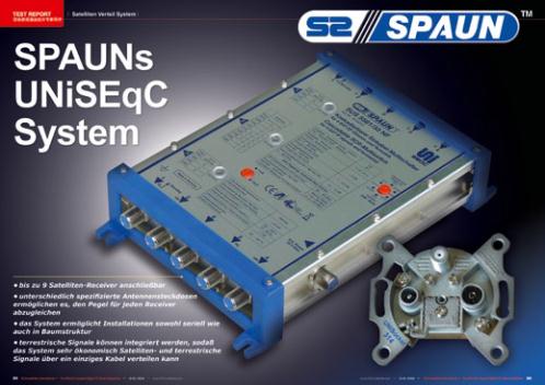
All these frequencies are
not only listed in the well
written and detailed user
guide but also on the top
cover of the SUS 5581/33
NF. Like all other SPAUN
multiswitches, also this unit
is perfectly finished off and
its labels could not be more
self-explanatory. You can see
it for yourselves in the pic-
tures presented alongside
this report.
The SCR multiswitch is
cascadable what means that
you can connect another
SUS 5581/33 NF to the trunk
outputs and increase the
number of the receivers in
the installation. Of course,
each receiver (or receiver
tuner) will be fully independ-
ent and capable of receiving
any channel from the satel-
lite your antenna, equipped
witha Quad or Quattro LNB,
is aimed at. While one multi-
switch should be a sufficient
solution for a family house,
you may need to cascade a
few multiswitches to serve a
multistory building.
Speaking of the distribu-
tion system configuration, it
is worth mentioning that you
are not limited to either 1x8
or 3x3 configurations. For ex-
ample, if you split the single
output to two lines, you can
get the configuration 2x4.
You only need to remember
that the splitter must sup-
port the IF frequency range
(950-2150 MHz) and have a
DC pass. This is clearly ex-
plained in the user guide.
An important thing you
should remember is that the
input signal from Quad or
Quattro type LNB should be
rather high (65~90 dBµV).
This is not a problem if you
are going to receive a strong
European satellite like AS-
TRA 1 on 19.2° and you have
enough room to install 90 cm
dish, but if this is a weaker
satellite, you should think of
either a bigger dish (what is
always advisable for a “col-
lective” reception) or an ad-
ditional amplifier between
LNB and SCR multiswitch
input.
A valuable feature of the
SUS 5581/33 NF is its ver-
satility in powering it up.
SPAUN supplies a wall mount
power supply unit but if this
is not practical in your instal-
lation, you can power the
multiswitch via its terres-
trial trunkline. By the way,
the included power supply
unit have a convenient plug
adapters what combined
with its high input voltage
range (100-240, V 50/60 Hz)
makes it truly worldwide.
There are also 5 pieces of
75 ohm terminators included
in the package. You attach
them to the trunk outputs if
they are not used for cascad-
ing.
Although the UNiSockets
are much simpler products
than the SCR multiswitch,
their performance also
counts in the whole system.
We got tree socket types.
Although they look identical
Download this report in
German
www.TELE-satellite.com/
TELE-satellite-1201/
deu
/spaun.pdf
except for the type number
printed on them, they dif-
fer in the insertion and tap
losses. UNiSocket 310 has
the lowest tap loss – only
10 dB, but its insertion loss
is the highest from the three
models – 3 dB. You’d better
choose this model for the
most distant socket from the
SCR switch. Model 318 has
the highest tap loss – 18 dB
but the lowest insertion loss
– only 1.5 dB. This model
should be considered for the
sockets located close to the
SCR multiswitch. UNiSocket
314 is an interim model with
moderate tap loss – 14 dB
and insertion loss – 2 dB.
All those parameters are the
typical values and according
to the product specifications,
you should be ready to ac-
cept +/- 2 dB tolerance of
the tap loss for every model.
We started our tests with
measuring the sockets. The
results were very satisfac-
tory for the insertion loss –
all three models had lower
average loss than specified.
Model 310 had the aver-
age insertion loss 2.49 dB,
model 314 – 1.99 dB and
model 318 – 1.66 dB. The
loss variation was small in
the whole IF frequency range
(950-2150 MHz). We can say
that the sockets were 0.5 dB
better than specified. When
we took the measurements
of the tap loss, the average
results were still in the speci-
fications: 11.96 dB for 310,
15.85 dB for 314 and 17.98
dB for 318. but slightly high-
er than typical value.
We built a test distribution
system then. A high output
power quad LNB was driving
our SUS 5581/33 NF. Later,
we switched to a Quattro
LNB and everything worked
equally good. The SCR mul-
tiswitch was configured for
one output. We connected
a quite long cable (over 30
meters) to its output. The
first UNiSocket 318 was con-
nected to the cable end and
after this socket we con-
nected the other seven ones:
2 x 318, 3 x 314 and 2 x
310. Between the sockets
we connected cables of vari-
ous lengths: from 30 cm to
6 meters. The whole system
from the SCR multiswitch
to the last socket measured
about 50-55 meters.
A cable of such length at-
tenuates the signal by about
15 dB and usually does not
pose a problem for a normal
satellite reception in which
an LNB is routed directly to
a receiver.