Basic HTML-Version


TEST REPORT on the Internet
134
TELE-satellite International — The World‘s Largest Digital TV Trade Magazine
— 12-01/2012
— www.TELE-satellite.com
Download this report in
English
www.TELE-satellite.com/TELE-satellite-1201/
eng
/globalinvacom.pdf
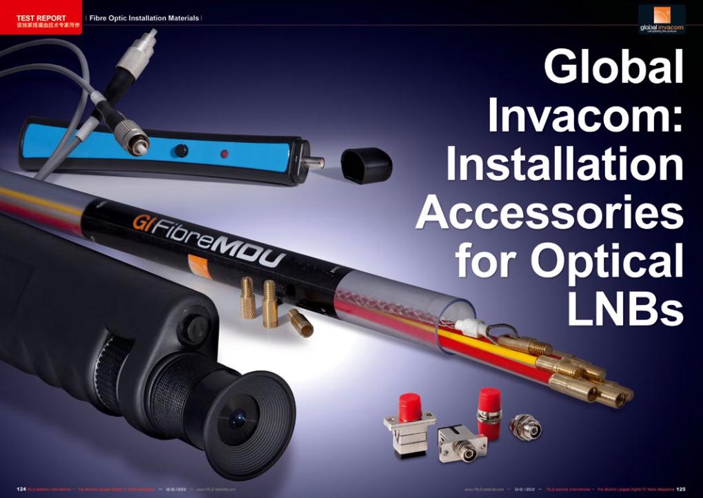
Fibre Optic Installation Materials
In 2008 TELE-satellite ran
an exclusive report on fibre
optic LNBs made by Glo-
balInvacom (TELE-satellite
04-05/2008). In the mean-
time this new technology
has turned into a serious
alternative to traditional
satellite reception systems
using coax cables. Even
more, fibre optic distribu-
tion technology will eventu-
ally become the new stand-
ard, once the first receivers
with an optical signal input
will come to market. Until
then, a converter will have
to be used to transform op-
tical signals back to electri-
cal signals for compatibility
with conventional receivers.
Yet, the benefits of fibre
optic technology are too
huge to ignore even today,
so that many professional
installers are already mak-
ing use of GlobalInvacom
technology.
In order to assist those –
and also less experienced
amateur users – GlobalIn-
vacom has launched some
very useful installation ac-
cessories that will add even
more shine to its optical
product line-up. After all,
most installers and private
users lack appropriate tools
to professionally work with
optical technology. While a
few F-plugs and some in-
sulation aids (a sharpened
knife will do just as nicely) is
all that is required for coax
cables, optical signal distri-
bution places much higher
demands on installers. But
before we go into greater
detail let’s first look at the
technical background of an
optical LNB and its advan-
tages: A conventional LNB
receives satellite signals
which are reflected from the
antenna’s focal point, then
converts those signals into
a lower frequency range
and transmits the convert-
ed signal right to the receiv-
er via a coax cable. Since
the frequency range a coax
cable can carry is quite lim-
ited in bandwidth (ranging
only from 950 MHz to 2150
MHz), two ‘tricks’ have to
be used in order to trans-
mit the entire frequency
spectrum of a satellite over
a single signal line. One of
those ‘tricks’ is signal polar-
ization, which can be either
horizontal or vertical. Based
on the control voltage sent
from the receiver via the
coax cable to the LNB, ei-
ther vertical (13 V control
voltage) or horizontal (18
V control voltage) signals
are transmitted. The sec-
ond ‘trick’ can be achieved
with the help of a 22 kHz
control signal which is used
to switch between low band
and high band frequencies.
For a typical direct-to-home
satellite the low band rang-
es from 10.7 GHz to 11.75
GHz, while the high band
covers 11.8 GHz to 12.75
GHz. If the receiver-gener-
ated 22 kHz control signal
is detected by the LNB it
transmits the high band fre-